6.2 Surface Infrastructure
6.2.1 Indicative Worst-Case Layout
- For the purposes of the NRA, the MDS for the Array layout considers installation of up to 280 surface structures, consisting of up to 265 wind turbines, up to three large Offshore Substation Platforms (OSPs) with up to 12 smaller OSPs. Although the final locations of infrastructure have not yet been defined, an indicative worst-case layout has been determined for shipping and navigation and is presented in Figure 6.2.
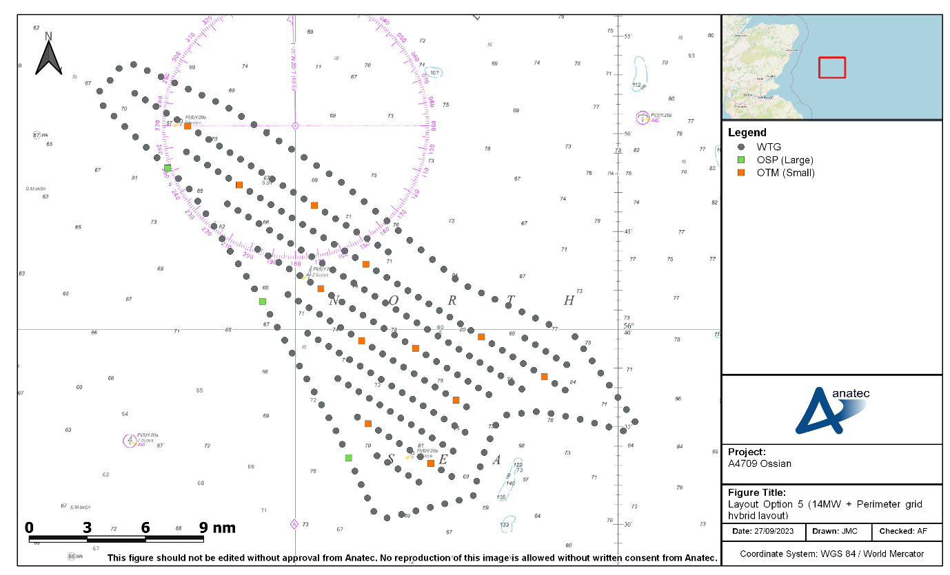
Figure 6.2: Indicative Worst-Case Layout for Shipping and Navigation
- As part of the worst-case layout for shipping and navigation, the three large OSPs are all located on the western boundary in proximity to regular routeing vessel traffic (see section 11).
- The indicative worst-case layout includes a dense perimeter to maximise passing allision risk. It is noted that the final layout may include a Single Line of Orientation dependent on ground conditions. The final layout including any proposal for a Single Line of Orientation will be discussed with the MCA post consent as per MGN 654 (MCA, 2021).
- The minimum spacing between structures is 1 km.
6.2.2 Wind Turbine Generators
- The wind turbines within the indicative layout each have a maximum rotor diameter of 236 m and maximum blade tip height (above Lowest Astronomical Tide (LAT)) of 266 m, noting that these values represent the MDS for shipping and navigation and do not necessarily represent the maximum parameters presented within volume 1, chapter 3.
- Semi-submersible floating foundations have been considered as the MDS for shipping and navigation as this foundation type has the largest surface dimensions (when assuming a layout with the largest number of wind turbines). The MDS wind turbine measurements assuming use of this foundation type are provided in Table 6.2.
Table 6.2: MDS for Shipping and Navigation – Wind Turbines
Parameter | MDS for shipping and navigation |
|---|---|
Foundation type | Semi-submersible floating foundations |
Dimensions at sea surface | 130×110 m |
Maximum blade tip height (above LAT) | 266 m |
Minimum blade clearance (above LAT) | 36 m |
Maximum rotor diameter | 236 m |
Maximum number of mooring lines per floating foundation | Six |
Highest connection point beneath waterline | 5 m below waterline |
Greatest angle of descent | 82 degrees from horizontal |
- As well as semi-submersible floating foundations, tension leg platforms (TLPs) are also under consideration as a foundation type, noting they would fall under the MDS assessed. Descriptions of each foundation type under consideration are provided in volume 1, chapter 3.
6.2.3 Offshore Substations
- For the purposes of the NRA, the MDS for shipping and navigation considers up to 15 OSPs, comprising three large OSPs and 12 smaller satellite OSPs, each with fixed jacket foundations. The large OSPs will have maximum topside dimensions of 121 m by 89 m, and the smaller satellite OSPs will have maximum topside dimensions of 41 m by 37 m. Topside dimensions, rather than foundation dimensions, have been used for the purposes of modelling as these are larger and therefore more conservative.