6.3 Subsea Cables
- Two types of subsea cables will be installed within the Array: inter-array and interconnector cables. Each of these are summarised in the following subsections.
6.3.1 Inter-Array Cables
- Inter-array cables will connect individual wind turbines to each other within the Array. Up to 1,261 km of inter-array cables will be required with the final length dependent on the final Array layout. The inter-array cable will include up to 116 km of dynamic cable located within the water column. Buoyancy modules and clump weights and tether clamps may be attached to the dynamic inter-array cable (subject to final design) to support the weight of the cable and maintain the ‘lazy-S’ configuration in the water column. Tether clamps and weighted anchors may also be required to limit the movement at the touch down area. A tether clamp is designed to secure subsea lines to an anchor on the seabed and usually comprises a steel housing that is bolted over the cable with a padeye to secure a chain to a weighted anchor on the seabed. Bend stiffeners help to reduce the fatigue in the inter-array cables, and are typically used where the cable exits the floating foundation and at touchdown points of the cable on the seabed. An indicative schematic of the inter-array cables is shown in Figure 6.3.
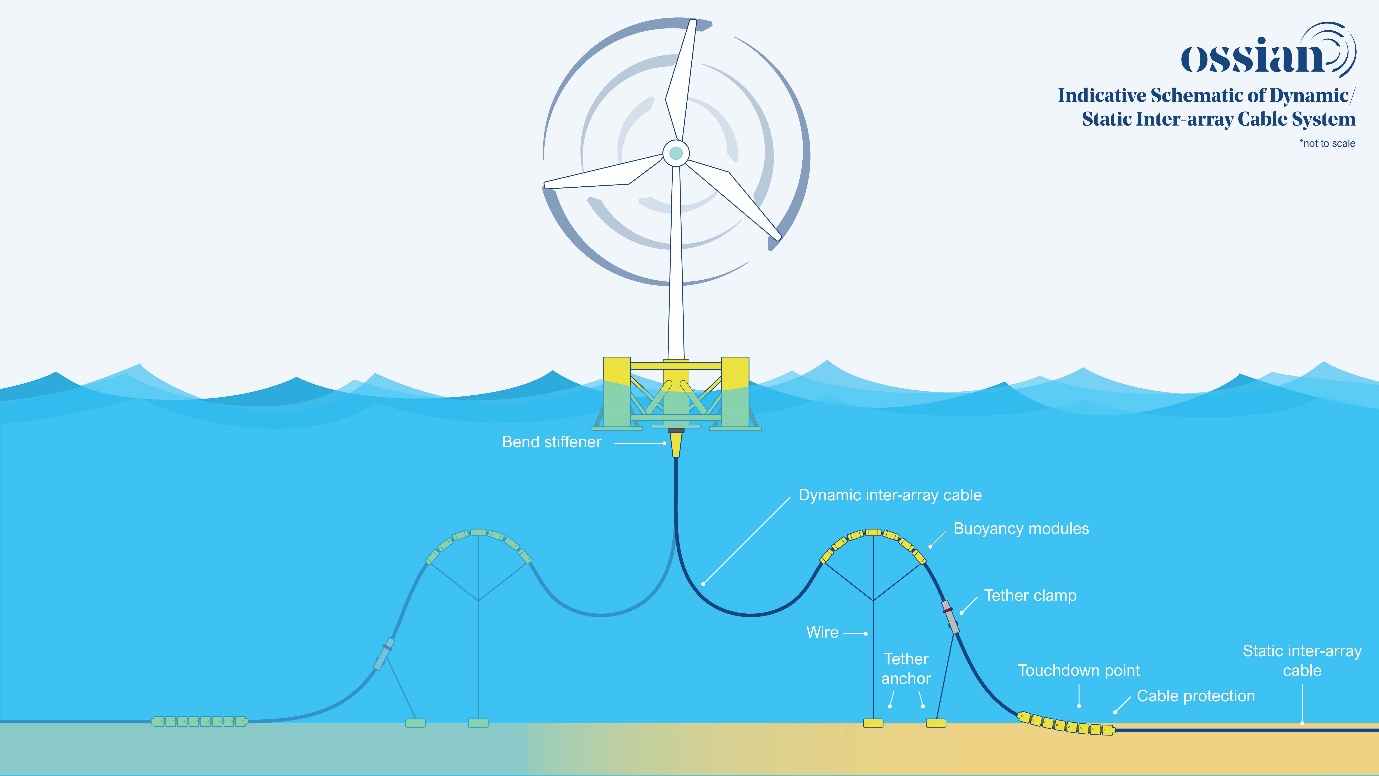
Figure 6.3: Indicative Schematic of the Dynamic/Static Inter-Array Cable System
6.3.2 Interconnector Cables
- Up to 12 interconnector cables will be installed within the Array, connecting the OSPs. They will have a combined total length of up to 236 km, with the final length dependent of the final Array layout. As the OSPs will be fixed there will be no dynamic cables associated with the interconnector cables.
6.3.3 Cable Burial and Protection
- Where practicable, the primary means of cable protection will be by seabed burial. The extent and method by which the static portion of the inter-array cables and the interconnector cables will be buried will depend on the results of a detailed seabed survey of the final inter-array and interconnector cable routes and associated Cable Burial Risk Assessment (CBRA). For both the static portion of the inter-array cables and the interconnector cables, the minimum burial depth is anticipated to be 0.4 m, subject to CBRA confirmation.
- Where target cable burial depths cannot be achieved, alternative cable protection methods may be deployed which will be determined within the CBRA. Further information on cable protection is provided in volume 1, chapter 3. Alternative cable protection will likely comprise a hard protective layer, such as graded rock or concrete mattresses. The need for this additional external protection will be subject to whether minimum target cable burial depths recommended for protection from the external threats can be achieved. In addition, Where the dynamic cable transitions to static (the transition point) some form of rock protection may be required.
- Cable burial and protection is captured in the embedded mitigation measures (see section 18.1).
6.4 Construction Timelines
- The offshore construction phase will last for approximately eight years.
6.5 Indicative Vessel and Helicopter Numbers
6.5.1 Construction
- Indicatively 7,902 return trips from construction vessels may be made throughout the construction phase, with up to 97 vessels on site at one time. These numbers are broken down in terms of activity in Table 6.3.
Table 6.3: Indicative Vessel Numbers During Construction Phase per Activity (Total Across Construction Period)
Construction Activity
| Indicative Number of Vessels | Indicative Number of Return Trips |
|---|---|---|
Main Installation Vessels (Jack-up Barge/Dynamic Positioning vessel) | 6 | 220 |
Cargo Barge / Heavy Transport Vessel (Self-propelled) | 9 | 421 |
Support vessels (Service Operations Vessel / Offshore Supply Vessel / Offshore Accommodation Vessel) | 10 | 1270 |
Tug/Anchor Handlers | 27 | 2059 |
Construction Support Vessels | 6 | 1353 |
Cable Installation Vessels (Cable Lay Vessel) | 3 | 236 |
Guard Vessels | 6 | 1026 |
Survey Vessels | 5 | 80 |
Crew Transfer Vessels | 6 | 770 |
Trenching Support Vessel | 3 | 189 |
Boulder clearance vessel | 3 | 42 |
Geophysical/geotechnical survey vessel | 4 | 50 |
Sand wave clearance vessel | 2 | 42 |
Unexploded Ordnance clearance vessel | 2 | 4 |
Pre Lay Grapnel Run Vessel | 2 | 64 |
Rock Dumping | 2 | 40 |
Dive Support Vessel | 1 | 36 |
Total | 97 | 7,902 |
- Up to 3,942 return trips from helicopters may be made throughout the construction phase, with up to seven helicopters on site at one time.